3D printing infill guide
3D Printing Infill Explained: Patterns, Density, Strength & Print Time
Two printed objects can look identical from the outside and behave nothing alike. One feels light and flexes slightly when you squeeze it; the other is heavy, rigid, and barely moves. The difference is almost entirely inside — in the internal structure your slicer generates between the solid outer walls. That internal structure is the infill.
Infill is one of the settings that most separates a print that suits its purpose from one that wastes material, takes far longer than it needs to, or fails under load it was never built for. It is also one of the settings beginners tend to get wrong by defaulting to the most, assuming more is always stronger. It usually is not, and understanding why is the point of this guide.
This guide explains what infill is, what infill percentage actually means, how common infill patterns behave, how density and pattern interact with strength, print time, and filament consumption, how much infill a given project tends to need, the practical difference between gyroid, grid, and cubic, why your walls often matter more than your infill, the mistakes beginners make, and a simple workflow for choosing infill settings in your slicer. The goal is to help you choose infill that matches the part's purpose rather than just the highest number.
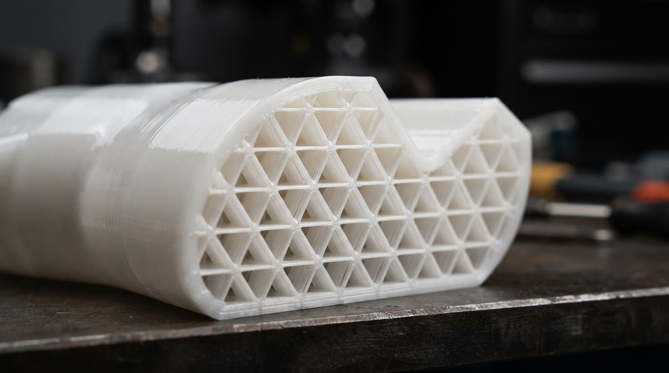
What Is Infill in 3D Printing?
In FDM (fused deposition modeling) and FFF (fused filament fabrication) printing, the machine builds a part one layer at a time by extruding melted filament along a path. Most parts are not printed completely solid. Instead, the slicer — the program that turns a 3D model into instructions for the printer — generates an outer shell of solid walls and solid top and bottom layers, then fills the volume between them with a repeating internal pattern. That internal pattern is the infill.
The walls (sometimes called perimeters or shells) and the top and bottom layers are what you actually see and touch. The infill sits hidden inside the part, acting as internal support that keeps the walls from collapsing inward and gives the part most of its internal structure. The combination of a solid shell and a partial internal fill is why an FDM part can feel rigid on the outside while being mostly hollow inside.
Infill is only one factor affecting how strong a printed part is. Wall thickness, layer adhesion, print orientation, material choice, and part geometry all matter — sometimes more than the infill itself. A part with thin walls and 50% infill can be weaker than one with thick walls and 15% infill, because the walls carry much of the load. Infill is a lever you can pull, but it is not the only one, and it is rarely the most efficient one to pull first.
Infill is generated by the slicer; it is not part of the original 3D model. Change the slicer, and the same model can produce a part with a different pattern and density inside it.
What Does Infill Percentage Mean?
Infill density is a slicer setting, usually expressed as a percentage from 0% (hollow) to 100% (solid). It controls how densely the internal pattern fills the volume between the walls. But it is a slicer setting — not necessarily an exact measurement of the final object's volume or exactly how much filament it consumes.
- 0% infill leaves the part completely hollow inside. Used for parts that only need an outer shell — vases, display objects, or parts where saving material and time matters more than strength.
- 10% infill is a light fill for parts that need some internal support but carry little load. Common for decorative objects and light household items.
- 15–20% infill is a widely used general-purpose range for functional but lightly loaded parts — organizers, mounts, and everyday brackets.
- 30–40% infill adds more internal structure for parts that see real handling or moderate load, where the print needs to survive repeated use.
- 50% infill is a heavier fill for parts under more deliberate stress, where you are deliberately trading time and material for durability.
- 100% infill makes the part effectively solid. It uses the most filament and takes the longest, and — unlike a part with strong walls and a lighter infill — it does not always make the part meaningfully stronger, especially for bending loads.
These are illustrative starting ranges, not guaranteed mechanical specifications. The actual relationship between the percentage on the slider and the part you hold depends on the pattern, the wall count, the material, the layer height, and the part geometry. Use the slicer's own time and material estimate — not a generic percentage — to predict the real result.
Common 3D Printing Infill Patterns
An infill pattern is the geometry the slicer uses to fill the interior. Each pattern has different structural and printing characteristics. Pattern names and availability can differ between slicing applications — what one slicer calls a particular pattern may not be identical to another's. The descriptions below describe the general tendencies of widely available patterns, not verified performance rankings.
| Pattern | General characteristics | Common uses | Tradeoffs |
|---|---|---|---|
| Grid | Crossing lines forming repeating squares; simple and fast. | General-purpose functional parts, everyday objects. | Intersections where lines cross can create build-up and slightly slower layers; can be less forgiving under directional loads than gyroid. |
| Gyroid | Wavy, twisting surfaces with no straight crossings; isotropic-ish structure. | Parts that take load from multiple directions; a popular default for strength. | More complex toolpaths than grid; can take a little longer to slice and print. |
| Cubic | Diagonal, three-dimensional structure spanning the volume; good load distribution. | Functional parts that carry load, including in more than one direction. | 3D geometry is more complex than a flat grid; can print slightly slower. |
| Triangles | Repeating triangular shapes; geometrically stable. | Parts where diagonal stability matters. | More directionally biased than gyroid; intersections can build up at higher densities. |
| Honeycomb | Hexagonal cells; efficient use of material for the structure it provides. | Lighter parts where you want strength relative to material use. | Often slower to print than grid; availability varies between slicers. |
| Lines | Parallel lines in one direction per layer, alternating between layers. | Very fast, light infill where speed and material saving matter most. | Weaker and more flexible than denser patterns; not a good choice for load-bearing parts. |
| Concentric | Rings that follow the part's outline; very sparse and light. | Display and decorative parts where weight matters most. | Offers the least internal structure; not suitable for functional or loaded parts. |
Grid
Grid infill is one of the simplest and fastest patterns: crossing lines form repeating squares. It is a reliable general-purpose choice and prints quickly because the toolpath is straightforward. Because the lines cross each other, the points where they intersect can collect a little extra material at higher densities, and the structure is more directional than a gyroid — it resists force differently along and across the lines.
Gyroid
Gyroid infill uses a wavy, continuously twisting surface with no straight crossings between layers. Its structure resists load more evenly across directions than a flat grid, which is why it has become a popular default for functional parts that might be stressed in more than one way. The tradeoff is a more complex toolpath, which can take a little longer to slice and print than grid.
Cubic
Cubic infill builds a three-dimensional diagonal structure that spans the volume rather than sitting flat in each layer. That gives it good load distribution, including for forces that are not purely vertical. It is a solid choice for functional parts, though the 3D geometry is more complex than a flat grid and can print slightly slower.
Triangles
Triangles repeat a geometrically stable shape, which can suit parts where diagonal stability matters. Triangles are more directionally biased than gyroid, and like grid, the points where lines meet can build up at higher densities.
Honeycomb
Honeycomb arranges material into hexagonal cells, which is an efficient shape — it provides good structure for the amount of material it uses. It is often slower to print than grid because of the more complex cell geometry, and its availability varies between slicers.
Lines and concentric
Lines infill uses parallel lines in one direction per layer, alternating between layers; concentric follows the part's outline as rings. Both are fast and sparse, and both are best treated as light, non-functional fill for display parts or objects where saving weight and time matters more than strength. Neither is a good choice for a part that carries load.
Not every pattern is available in every slicer, and implementations with the same name can differ. PrusaSlicer and OrcaSlicer both offer gyroid, grid, and cubic; UltiMaker Cura includes grid, lines, and other patterns among others. Verify what your slicer offers and how the option behaves before committing to it for a load-bearing part.
How Infill Affects Print Strength
A part's real strength comes from the combination of infill density, the infill pattern's geometry, wall count, layer adhesion, print orientation, the material, and the direction of the load. Changing infill density alone is rarely the whole story.
- Higher infill density generally adds material and internal structure, which tends to increase strength — but not linearly, and not for every type of load.
- Wall (perimeter) count often contributes more to strength than infill, especially for bending and impact loads. Two extra walls can do more for rigidity than a large jump in infill.
- Layer adhesion — how well each layer bonds to the one below it — is a major factor in strength along the Z axis and depends heavily on the material, nozzle and bed temperature, and printing conditions. Poor adhesion weakens a part regardless of infill.
- Print orientation matters: a part laid flat is strong where the layers are continuous and weaker along the layer lines. Reorienting a part can change its strength more than changing infill.
- The direction of the load matters more than the infill percentage. An infill pattern that resists force well in one direction may flex in another, which is why an isotropic-ish pattern like gyroid is often a safer default for parts loaded unpredictably.
- Material selection sets the ceiling. A tough, well-adhered engineering filament at modest infill can outperform a brittle material at high infill for many real loads.
There is no universal engineering rule that a given infill percentage guarantees a given strength. For any part that carries real, safety-critical, or repeated load, treat slicer settings as a starting point and validate the actual part for the actual load — not as a guarantee.
How Infill Affects Print Time and Material Use
In general, higher infill density means more material to extrude and more travel for the nozzle, which means a longer print and more filament consumed. More complex patterns — gyroid, cubic, honeycomb — usually take a little longer than a simple grid or lines for the same density, because the toolpath is more intricate even though it uses material efficiently.
The relationship is not proportional, and it is not always intuitive. Moving from 15% to 20% infill is a small change in time and material; moving from 40% to 100% is a large one, and on parts with thick walls the infill may be a minority of the total material even at higher densities. The walls and solid top and bottom layers consume filament too, and on many parts they consume more than the infill does.
This is why your slicer's own time and material estimate is more useful than any generic rule of thumb. The slicer knows the exact part geometry, the wall count, the layer height, and the chosen pattern, and it estimates both the print duration and the filament weight for that specific combination. Compare those estimates between settings rather than predicting from the percentage on the slider alone.
A faster, sparser print is not automatically a worse part. For many objects — organizers, enclosures, jigs, display pieces — the load is light, and a 15–20% gyroid or grid infill with sensible walls is plenty. Spending the time and material on more infill than a part needs is wasted, not safer.
How Much Infill Do You Actually Need?
The right infill depends on what the part does, not on a single number. These are conceptual examples to calibrate your thinking — not guaranteed specifications, and not a substitute for testing a part under the load it will actually see.
- Decorative models and display objects. Vases, sculptures, and parts that only need to look right and hold their own shape can use a light infill (10% or less) or, for some shapes, none at all. The walls carry everything.
- Basic household accessories. Organizers, drawer inserts, and light mounts that see handling but little real load are well served by a general-purpose range like 15–20% with a standard pattern and a couple of walls.
- Functional brackets and mounts. Parts that hold something, clamp to something, or carry moderate load benefit from a denser fill — often 30–40% — and an eye to wall count and orientation. Gyroid or cubic is a reasonable starting point for parts loaded in more than one direction.
- Prototypes and iterations. Early prototypes that exist to test fit and form can often use a lighter infill to iterate faster and cheaper; you can always print a stronger final version once the design is settled.
- Heavily loaded parts. Parts under deliberate or repeated stress can justify 50% or more — but pair it with adequate walls, the right material, and the right orientation, and treat the settings as a starting point to validate, not a guarantee.
Casual hobby applications are very different from safety-critical or load-bearing ones. Slicer settings do not establish the safety of a structural component on their own. For anything that must not fail under load — a bracket holding weight, a part on moving equipment, anything protective — validate the actual printed part for the actual load, and when in doubt consult someone qualified for the specific application.
Gyroid vs. Grid vs. Cubic Infill
These three are among the most common functional-infill choices, and the practical differences come down to geometry, how each resists load, printing characteristics, and typical use.
Geometry
Grid lays out crossing straight lines in a flat, repeating square pattern. Cubic builds a diagonal, three-dimensional structure that spans the volume across layers. Gyroid generates a continuous wavy surface with no straight crossings, twisting through the volume. Each fills the same space with a different internal architecture.
Directional behavior
Grid is more directional — it resists force differently along and across the lines. Cubic distributes load across more of the volume and resists force in more than one direction. Gyroid is often described as close to isotropic for a printed part, resisting load more evenly across directions, which is why it is a popular default for parts that might be stressed unpredictably.
Printing characteristics
Grid is the simplest and usually fastest to print. Cubic and gyroid use more complex 3D toolpaths that can take a little longer to slice and print, with gyroid often printing smoothly but with more motion. At higher densities, the crossing points in grid and the intersections in some patterns can create slight build-up.
Typical use and limits
Grid is a dependable general-purpose choice where you want simplicity and speed. Cubic suits functional parts that benefit from distributed, multi-direction load handling. Gyroid is a common pick for parts where strength in any direction matters more than minimum print time. None is a universal winner — the best choice depends on the part and the load.
If you are not sure, a mid-range gyroid or grid with good walls is a safe, widely used starting point. The slicer's preview will show you the actual toolpath and let you compare the result before you print.
Infill vs. Walls: Which Matters More?
Beginners often reach for infill when a part needs to be stronger, but the outer walls frequently contribute more to a print's real mechanical behavior than the infill does. The walls form the continuous outer structure that takes most of the impact, bending, and surface load — the infill mostly keeps those walls from collapsing inward and adds internal support.
For bending and impact loads especially, adding a wall or two (going from two perimeters to three or four) can make a part noticeably more rigid for less time and material than a large jump in infill. The walls are continuous where infill is partial, and continuity is a big part of how a printed part resists being bent.
A practical example
Consider a simple printed bracket that needs to hold a modest load without flexing. Print it with thin walls and 50% infill and it may still feel soft at the edges because the walls are the weak point. Print the same bracket with an extra wall or two and 15–20% infill and it will often feel more rigid, print faster, and use less filament — because the continuous walls are now doing the structural work the infill was trying and failing to do. The lesson is not that infill is unimportant, but that walls are usually the first lever to pull when a part needs to be stronger.
This is why it rarely makes sense to run 100% infill with thin walls. Before pushing infill up, check your wall count and orientation — those often buy more real strength per gram of filament.
Common Infill Mistakes Beginners Make
Most infill mistakes come from treating infill as the only strength lever, or from assuming the slicer setting maps cleanly onto real-world performance. These are the common ones to avoid.
- Automatically choosing 100% infill. A solid print uses the most material and takes the longest, and for many loads it is not meaningfully stronger than a part with good walls and a lighter infill.
- Ignoring wall thickness. Walls often contribute more to strength than infill; increasing infill with thin walls is a common, inefficient fix.
- Choosing settings without considering load direction. A pattern that resists force well in one direction may flex in another — match the pattern to how the part will actually be loaded.
- Assuming more infill always means more strength. The relationship is not linear and is not the only factor; material, adhesion, and orientation often matter more.
- Ignoring the slicer preview. The preview shows the actual toolpath, time, and material for your specific part — skipping it means guessing at the result.
- Copying settings without considering the material. Different filaments behave differently; a setting that works for one material may not be appropriate for another.
- Using hobby recommendations for safety-critical parts. Slicer settings are a starting point, not a certification. For anything load-bearing, validate the actual part under the actual load.
How to Choose Infill Settings in Your Slicer
A simple workflow keeps the choices in order. Not all slicers use identical controls or names, but the same logic applies across PrusaSlicer, OrcaSlicer, UltiMaker Cura, and similar software.
- Identify the part's intended use. A display object, a light mount, and a loaded bracket want very different infill.
- Consider the material and the part's print orientation, since both affect how the infill behaves under load.
- Choose a pattern that fits the load. A general-purpose grid or gyroid is a safe starting point for functional parts; lines or concentric for light, non-structural fill.
- Select a starting density from the ranges above that matches the use case, not the highest number.
- Review the wall and top/bottom layer settings. For strength, check wall count before raising infill.
- Preview the sliced model. Look at the actual infill geometry and the time and material estimates.
- Compare a couple of settings using the estimates to see the real tradeoff in time and filament for your specific part.
- Print and evaluate a non-critical prototype before committing to settings for a part that matters.
- Adjust as needed — based on how the printed part behaves, not on assumptions from the percentage alone.
Use the slicer's documentation for the exact controls and option names in your version. The workflow is the same across slicers; the interface and availability of specific patterns are not.
Frequently asked questions
Final Thoughts
Infill is one of the most useful levers in FDM printing, and one of the most misunderstood. It is not a simple 'more is stronger' dial. The best infill choice depends on the part's purpose, the material, the geometry, the print orientation, and the load it will actually see — and on how all of those interact with the walls, which often matter more than the infill itself.
More infill is not automatically better, and 100% is rarely the right answer for a functional part. A well-chosen pattern at a sensible density, paired with adequate walls and the right orientation, usually gives a stronger, faster, and more material-efficient part than defaulting to the maximum. Let the slicer's preview and estimates guide the real tradeoff, validate any part that carries real load, and choose infill that matches the work the part actually has to do.
Keep reading
- 3D Printing hub — all 3D-printing guides and basics
- 3D Printers for Beginners: what to know before buying
- How Much Does a 3D Printer Cost?
- FDM vs. Resin 3D Printing — which fits your projects?
- Are 3D Printers Worth It?
- 3D Printer Accessories: what you actually need
- Material Compatibility Database
- Editorial Policy — how we research and publish
Digital Workshop Guide does not claim hands-on testing, ownership, or measured performance for any infill pattern, percentage, or printed part described here. Explanations are based on FDM/FFF printing fundamentals and the published documentation of major slicing software as of October 2026 — not on independent benchmarking. No pattern is ranked or recommended as a universal winner, and no strength, time, or filament figure is presented as a measured result. Verify pattern availability and behavior in your own slicer, and validate any part that carries real load.